
Single Channel Relay Module

Written by
Atribot team
Last updated
June 10, 2026
Introduction
How can a small microcontroller safely control a high-voltage light bulb, fan, or home appliance? Since most microcontrollers operate at low voltages and currents, they cannot directly switch high-power devices. This is where a Relay Module becomes useful.
A Single Channel Relay Module acts as an electrically controlled switch that allows low-voltage devices such as Arduino boards, ESP32s, and Raspberry Pis to control high-voltage or high-current loads safely. By isolating the control circuit from the load circuit, the relay provides a reliable and secure method for switching electrical devices.
Because of its simplicity, affordability, and versatility, the relay module is widely used in home automation, industrial control systems, IoT projects, and smart appliances.
In this article, you will learn about the relay module's main parts, pin configuration, technical specifications, working principle, advantages, disadvantages, and real-world applications.
Main Parts
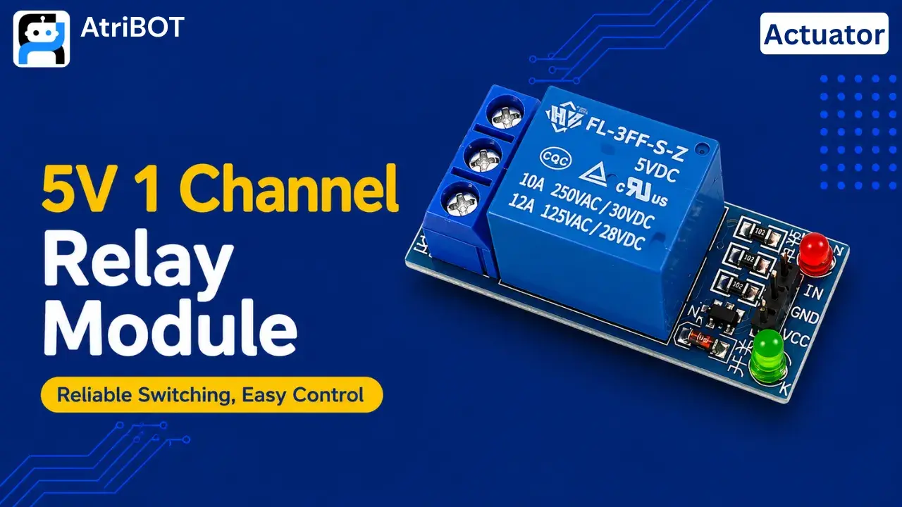
A typical Single Channel Relay Module consists of several components that work together to safely switch electrical loads using low-voltage control signals.
Electromagnetic Relay: The relay is the primary switching component on the module. Inside the relay, an electromagnetic coil controls a set of mechanical contacts. When the coil is energized, the contacts change their position, allowing the connected load to be switched ON or OFF.
Optocoupler: Many relay modules include an optocoupler to provide electrical isolation between the microcontroller and the relay circuit. This helps protect sensitive electronics from voltage spikes and electrical noise.
Driver Transistor: The transistor acts as an electronic switch that controls the relay coil. Since microcontroller pins cannot provide enough current to energize the relay directly, the transistor amplifies the control signal and drives the relay coil.
Flyback Diode: The flyback diode protects the circuit from the reverse voltage generated when the relay coil is switched OFF. Without this protection, voltage spikes could damage the transistor and other components.
Indicator LEDs: The relay module usually includes power and status LEDs. These LEDs provide a visual indication of whether the module is powered and whether the relay is currently activated.
Screw Terminals: The screw terminals provide secure connections for external electrical loads. They are used to connect appliances, lights, motors, and other high-power devices to the relay contacts.
Input Header Pins: These pins allow the relay module to connect to a microcontroller. They receive power and control signals required for relay operation.
Pinouts
A standard 5V Single Channel Relay Module contains six connection terminals divided into control and load sections.
Control Side Pins
Pin | Description |
|---|---|
VCC | Power Supply (5V) |
GND | Ground |
IN | Control Signal Input |
Relay Output Terminals
Terminal | Description |
|---|---|
COM | Common Terminal |
NO | Normally Open |
NC | Normally Closed |
VCC Provides power to the relay module and control circuitry.
GND Acts as the common ground connection.
IN Receives the control signal from a microcontroller or logic circuit.
COM: The common terminal used for switching the connected load.
NO()Normally Open): The NO terminal remains disconnected from COM until the relay is activated.
NC(Normally Closed): The NC terminal remains connected to COM when the relay is inactive.
Specifications
Parameter | Specification |
|---|---|
Operating Voltage | 5V DC |
Relay Type | SPDT (Single Pole Double Throw) |
Number of Channels | 1 |
Trigger Voltage | 5V Logic |
Switching Current | Up to 10A |
Switching Voltage (AC) | 250V AC |
Switching Voltage (DC) | 30V DC |
Control Interface | Digital Input |
Isolation | Optocoupler (varies by model) |
Indicator LEDs | Power and Status LEDs |
Working Principle
The Single Channel Relay Module works by using an electromagnetic relay to control high-voltage or high-current devices through a low-voltage control signal. When a microcontroller such as an Arduino sends a signal to the relay module's IN pin, the driver circuit activates the relay coil.
Control Signal Received: When a HIGH or LOW trigger signal is applied to the IN pin (depending on the module type), the relay module receives the command to switch the connected load.
Relay Coil Energized: The driver transistor allows current to flow through the relay coil, generating a magnetic field inside the relay. This magnetic field creates the force required to move the internal switching mechanism.
Contact Switching: As the magnetic field increases, it attracts the relay's armature and changes the position of the internal contacts. The Common (COM) terminal disconnects from one contact and connects to the other, either NO (Normally Open) or NC (Normally Closed).
Load Activation: Once the contacts switch position, electrical current can flow through the connected device. This allows the relay module to turn appliances, lights, motors, or other electrical loads ON or OFF.
Relay Deactivation: When the control signal is removed, the relay coil loses power and the magnetic field disappears. A spring mechanism then returns the contacts to their original position, restoring the relay's normal state.
This switching process allows a low-power microcontroller to safely control high-power electrical devices while maintaining electrical isolation between the control circuit and the load circuit.
Advantages & Disadvantages
Relay modules are widely used because they provide safe and reliable switching between low-voltage control circuits and high-voltage loads. However, they also have certain limitations.
Advantages
Easy to interface with microcontrollers
Can control high-voltage devices
Provides electrical isolation
Reliable switching operation
Low cost
Suitable for AC and DC loads
Simple control using digital signals
Widely available
Disadvantages
Mechanical contacts wear over time
Slower than solid-state relays
Produces clicking sounds during operation
Larger than semiconductor switches
Higher power consumption compared to electronic switching devices
Applications
Relay modules are widely used in automation and control systems where low-voltage electronics need to control high-power devices.
Home Automation: Relay modules are commonly used to control lights, fans, and household appliances through microcontrollers and IoT systems.
Smart Lighting Systems: Relay modules allow automatic control of lighting based on sensors, timers, or mobile applications.
Industrial Automation: Factories use relay modules to switch machines, motors, and control equipment safely.
Smart Irrigation Systems: Relay modules control water pumps and valves based on soil moisture sensor readings.
Security Systems: Relay modules are used to activate alarms, sirens, and access control devices.
IoT Projects: Relay modules enable remote switching of electrical devices through Wi-Fi, Bluetooth, and cloud-based platforms.
Automatic Door Systems: Relay modules control door locks, motors, and actuators in automated entry systems.
Motor Control Applications: Relay modules are used to switch motors and other high-current devices safely.
Appliance Control: Home appliances such as heaters, pumps, and air conditioners can be controlled through relay modules.
Educational Electronics Projects: Relay modules help students learn about electrical switching, automation, and microcontroller interfacing.
The Single Channel Relay Module is one of the most important actuator modules in electronics, providing a safe and effective way to control high-power devices using low-voltage control systems.